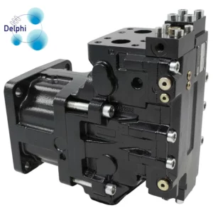
When troubleshooting a F11 Series Motor that is not delivering the expected flow, it’s essential to systematically analyze and address potential issues. Here is a step-by-step guide for troubleshooting:
- Check Fluid Level:
- Ensure that the hydraulic fluid level is adequate. Low fluid levels can result in reduced flow.
- Inspect Filters:
- Check hydraulic filters for clogs or contamination. Dirty filters can restrict flow. Replace or clean filters as needed.
- Examine Hoses and Connections:
- Inspect hydraulic hoses for leaks, kinks, or blockages. Ensure all connections are secure and free of leaks.
- Verify Pump Speed:
- Check the speed of the pump driving the F11 Series Motor. Ensure it is operating at the correct speed as specified by the system requirements.
- Adjust Displacement Setting:
- If the F11 motor has an adjustable displacement setting, verify that it is set to the correct value for the application. Adjust if necessary based on the system requirements.
- Check Pressure Settings:
- Verify that the system pressure settings are within the recommended range for the F11 motor. Incorrect pressure settings can affect flow.
- Inspect Control Valves:
- If the motor is controlled by hydraulic valves, check for proper operation of control valves. Ensure that the valves are not stuck and are responding correctly to signals.
- Examine Relief Valve Settings:
- Check the relief valve settings. If the pressure relief valve is set too low, China F11 Series Motor supplier it can cause a drop in flow. Adjust as needed.
- Evaluate System Temperature:
- High operating temperatures can affect the viscosity of hydraulic fluid and, consequently, the flow rate. Monitor system temperature and address cooling issues if necessary.
- Check for Mechanical Binding:
- Inspect the motor and associated components for any mechanical binding or physical obstructions that may impede the movement of internal parts.
- Perform Flow Testing:
- Use flow meters or hydraulic testing equipment to measure the actual flow at various points in the system. Compare these measurements to the expected flow rates.
- Inspect the Motor:
- If possible, open the motor for a visual inspection. Check for any damage, wear, or contamination within the motor. Pay attention to internal components like pistons and swash plates.
- Consult Manufacturer Documentation:
- Refer to the manufacturer’s documentation, technical specifications, or service manual for the F11 Series Motor for specific troubleshooting guidance and recommended procedures.
- Seek Professional Assistance:
- If the issue persists or if you are unsure about the diagnosis, consider seeking assistance from the manufacturer’s technical support or a qualified hydraulic system technician.
Remember to follow proper safety procedures when working with hydraulic systems, and always consult the manufacturer’s guidelines for maintenance and troubleshooting.
What is the purpose of the F11 Series Motor case drain line, and how is it configured?
The case drain line in a hydraulic system, including that of the F11 Series Motor, serves an important purpose related to the lubrication and protection of the motor. The case drain line is designed to manage and redirect excess hydraulic fluid that has passed through the motor’s internal components, particularly the motor’s case, back to the hydraulic reservoir or another appropriate location. Here’s a breakdown of the purpose and configuration of the case drain line:
Purpose of the Case Drain Line:
- Lubrication and Cooling:
- The F11 Series Motor, like many hydraulic motors, relies on hydraulic fluid for lubrication and cooling. As the hydraulic fluid circulates through the motor’s internals, it lubricates moving parts and helps dissipate heat generated during operation.
- Pressure Equalization:
- Hydraulic motors, especially those with high-pressure capabilities like the F11 Series, may have pressure imbalances across their internal components. The case drain line helps equalize pressure by allowing excess fluid to exit the motor.
- Contamination Control:
- The case drain line plays a crucial role in preventing contamination. If any internal seals wear or if there is internal leakage, the case drain line carries away the leaked fluid. This helps prevent contamination of the hydraulic fluid in the system.
Configuration of the Case Drain Line:
- Connection to Motor Case:
- The case drain line is typically connected to a port on the motor’s case, allowing excess fluid to exit.
- Routing to Reservoir:
- The other end of the case drain line is routed to the hydraulic reservoir or another designated location. It is important that the fluid is returned to a location where it can be properly filtered and reused in the system.
- Use of Check Valve:
- Some hydraulic systems may incorporate a check valve in the case drain line. China F11 Series Motor suppliers This valve allows fluid to flow from the motor to the reservoir but prevents backflow, maintaining system integrity.
- Filtering:
- In some setups, a filter may be installed in the case drain line to capture any particles or contaminants that may have entered the system. This helps maintain the cleanliness of the hydraulic fluid.
- Size and Material:
- The size and material of the case drain line are chosen to handle the flow rate and pressure requirements of the specific hydraulic system. The line should be resistant to wear and corrosion.
It’s important to follow the manufacturer’s guidelines and specifications when configuring the case drain line for an F11 Series Motor or any hydraulic motor. Proper installation and maintenance of the case drain line contribute to the overall efficiency and longevity of the hydraulic system.
